
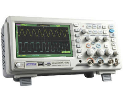
ATTEN ADS1102CML 100Mhz Digital Oscilloscope
1.Color TFT(320x234)5.7 inch LCD screen
2. Memory depth of ADS1000 is 4K and that of ADS1000M is 2M
3. if the buyers need to know discount price,please send e-mail to us.
Note:
If your shipment is deliveyellow to a remote area,this charge will be added to your shipping cost.Checking your area is a remote area or is not a remote area on the website:http://remoteareas.dhl.com/jsp/first.jsp
Main Features
1.500Msa/s & 1Gsa/s Sampling Rate
2.2 Channels
3.7����Widescreen LCD Color Display
4.8x18 div time window
5.USB Host/Device:Support USB Printer and USB Flash Drive
6.PictBridge Software
7.12 Language
8.Screen saver function
Applications:
1.Industial Power Design,Troubleshooting,and Maintenance
2.Electronics Design,Troubleshooting,Installation,and Maintenance
3.Circuit Design & Debug
4.Educational Lab & Training Institutions
5.Repair & Service
6.Production Test & Quality Inspection
2.Specification:
Technical Characteristic:
1. The highest Single real-time sampling rate can up to 1Gsa/s;Equivalent sampling rate is up to 50Gsa/s
2. Memory Depth:CML Series:2Mpts,realized via special data recorder
3. Max recording length:6Mpts,realized via special data recorder
4. Trigger types:Edge,Pulse Width,Video,Slope,Alternative
5. Unique Digital Filter function and Waveform recorder function
6. No loss of bandwidth when using CH2 and long memory at the same time
7. Support Pass/Fail function
8. Thirty two parameters Auto measure function
9. Save/recall types:Setups.Waveforms,CSV file,Picture
10. Waveform Indensity and Grid Brightness can be adjusted
11. User Inerface in 12 Languages
12. Standard Configuration Port
USB Host:Support USB flash driver save/recall function and update firmware;
USB Device:Support PictBridge compatible printer and support PC remote control;RS232,Pass/Fail output.
USB Device:Support PictBridge compatible printer and support PC remote control;RS232,Pass/Fail output.
Model |
1202CL+ |
1202CML |
1152CML |
1102CML |
1062CML |
1042CML |
1022CL+ |
| Bandwidth | 200MHz |
150MHz |
100MHz |
60MHz |
40MHz |
25MHz |
|
| Sampling Rate | 500Msa/s |
1Gsa/s |
500Msa/s |
||||
| Equvalent | 50Gsa/s |
10Gsa/s |
|||||
| Memory | 5Kpts/CH |
Single Channel:2Mpts;Double Channels:1Mpts |
40Kpts |
||||
Rise Time |
<1.8ns |
<2.3ns |
<3.5ns |
<5.8ns |
<8.8ns |
<14ns |
|
| Input Impedance | 1M Ohm ||17Pf |
1M Ohm ||14Pf/50O |
1M Ohm ||17Pf |
||||
| ? | ? | ? | ? | ||||
| Sec/div Range | 2.5ns/div-50s/div |
5ns/div-50s/div |
10ns/div-50s/div |
2.5ns/div-50s/div |
|||
Scan:100ms-50s/div |
|||||||
| Display | 7 inch LCD Color(480*234) |
||||||
| For years I have been using my trusty?PicoScope 2105?for my electronics hobby needs. The PicoScope did a fine job, but the 2105 was a bit limited in bandwidth (25MHz) and has a real time sampling rate of only 100MSa/sec. The biggest drawback with the 2105 was that it had only one channel, preventing me from taking measurements such as propagation delay or comparison of input vs. output signals. It was time for an upgrade - I wanted something stand-alone, that did not rely on my PC or laptop. Something with knobs that could be adjusted while looking at the display and not having to click on a drop-down box to select a new time base or voltage scale. My main criteria was that the oscilloscope should have:
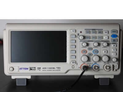
After looking around, I decided that I'd give the Atten ADS1102CML the benefit of the doubt. The specs looked fine and the bigger 7" screen was certainly attractive. I ordered it from?GSMserver.com?in Hong Kong (who were professional and gave excellent service) for US$530.00. It arrived here in South Africa two weeks later. This is by no means a comprehensive review, but I will try to give a fair overview of the scope's performance.?Timings, performance and waveforms captured on the ADS1102CML were compared/verified with a?150MHz HP?DSO and a 400MHz 10X Tek probe. I also did some comparisons with a Rigol DS1052E, which I borrowed from a friend. Note that the?Atten ADS1102CML?is also marketed as the?Siglent SDS1102CML?and in South Africa it is sold by?Communica?as the?Xytron DSO1102CML?oscilloscope. Siglent is the original designer of the 1102CML series. |
-
Review?of the scope's various functions
-
Bugs?in the older Atten ADS1102CML firmware
-
Things I like?about the scope
-
Things that annoy me?about the scope
| Software version |
3.01.01.213 |
| Updated version |
3.01.01.31R16 (download here) |
| Hardware version |
6-41-2.0 |
| EasyScope version |
3.0 (download here) |
Here is a Youtube video I made, showing how to use the oscilloscope to measure the effects of decoupling capacitors on a circuit:
Decoupling capacitors and the 555 timer IC
|
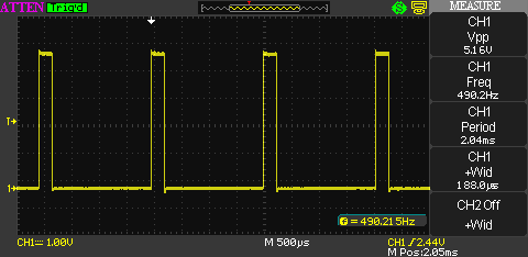
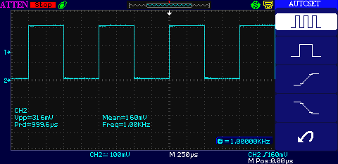
The scope boots in approximately 14 seconds to the point where it is ready to display waveforms. This image shows the 1kHz calibration signal generated by the scope itself and the auto-set button was pressed. The soft-keys allow you to instantly measure frequency, pulse width, rise time and fall time of the signal. Note that I ran the self-calibration function after unpacking the scope. The self-calibration takes 1 minute and 20 seconds to complete. The Rigol takes 5 minutes and 10 seconds to complete self-calibration. |
|
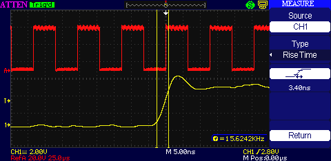
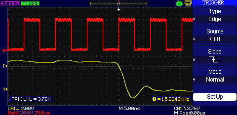
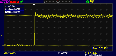
I fed the scope a 15.6kHz signal (divided down from 32MHz by a 74HC4040 binary counter) and activated the Ref signal storage. I then decreased the time base all the way down to 5ns/div in order to measure the rise time of the 4040's output. The probe was set to 10X for better freq. response. The rise time is correctly measured at 3.40ns. Bug: the RefA waveform shows an incorrect scale of 20V/div if the probe input is set to 10X. The Ref scale is correct for a 1X probe configuration. Fixed: latest firmware no longer has this problem. |
|
I've read reports of the Siglent scopes not triggering correctly at low voltages on the down slope, but I could not simulate the problem at any frequency. I changed the trigger slope to falling edge an tested triggering at high signal levels and at low signal levels (next frame). The triggering works as expected. |
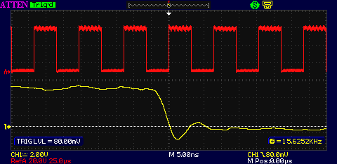 |
Even at a very low trigger voltage? of 80mV the triggering still works fine. |
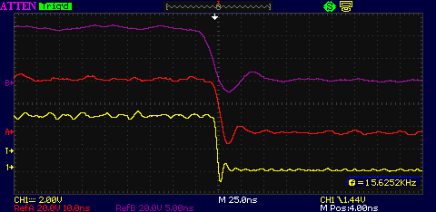 |
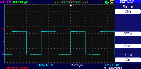
I added two new Ref waveforms, RefB at 5ns, RefA at 10ns and the live waveform was set to 25ns. The Ref waveforms display fine, but once they've been captured one cannot move them up or down, nor zoom in on the Ref waveform's timebase. This is expected behavior and allows waveform comparisons at different time bases. |
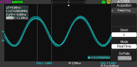 |
Detecting and measuring noisy signals is important to me. I recently ordered an Epson 64MHz oscillator from RS. These oscillators are pre-programmed at the factory to a certain frequency, but it quickly became apparent that the output is very noisy and although the clock source is stable, the output is not very pretty. The oscillator output wavers and no single wave cycle is the same as before. Switching on persistence lets me see how much the oscillator is wavering. This at the shortest time base of the ADS1102CML. |
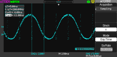 |
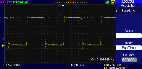
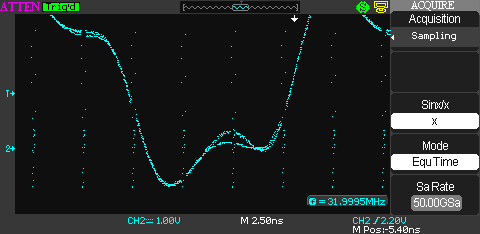
Using the same oscillator, I switched the scope to EquTime mode and was presented by the screen to the left. Note that, for the most part, the scope correctly plots the waveform and shows the noisy state of the oscillator output. I verified the waveform on my 150MHz HP scope and the wave looks the same,?except?for the vertical dotted lines every 5ns. These vertical lines are what I believe to be a firmware bug (I'm hoping it is not a hardware bug). Fixed: after warm-up and recalibration the random dots at 5ns intervals are no longer present. |
 |
The 64MHz signal divided by two using the 4040 on a breadboard. The breadboard introduces some additional capacitance resulting in the signal you see to the left. |
 |
I fired up my Arduino and played around with the analogue outputs. I added 4 measurements on the measurement bar on the right. On the Rigol you can only add 3 custom measurements as a time (due to the limited display width). The voltage, frequency, period and pulse-width match exactly with what the HP scope measures. |
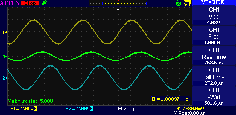 |
I used the Math function to add together two sine waves that were out of phase. It works well and the result shown is accurate. It must be noted that the scope does not allow measurements on the resulting math waveform (but neither does the Rigol or the HP). |
 |
Back to measuring the 1kHz calibration wave along with a few measurements added on the measurement bar. |
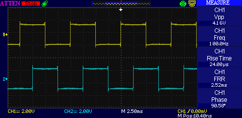 |
I introduced a square wave at 100Hz (produced by my PC sound card and the?Sound Card scope?software). I set the software to phase-shift the second signal by 90 degrees and added a phase measurement to the measurement bar. It correctly measures the phase shift as well as the FRR time between the two waveforms. |
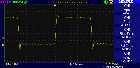 |
Back to a 4MHz signal measured directly on the output pin of a 4MHz crystal oscillator can. The ringing you can see is also shown on the HP, but not so much on the Rigol (mostly due to the fact that the ringing signal is >50MHz which the Rigol cannot measure). |
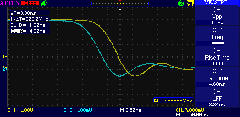 |
This is a way cool experiment! I connected two probes to the oscilloscope and measured the same 4MHz signal on both channels. The difference in time between the two signals is caused by one probe having a 2m length and the other probe having a 1.2m length. Since electricity travels roughly 20cm every nanosecond, the time difference of 3.3ns between the two falling edges is almost exactly right. Note that I used EquTime mode for this measurement. |
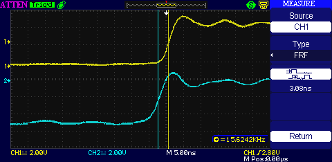 |
The left measures the propagation delay between two outputs of the 74HC4040 binary?ripple counter going high. The scope clocks it at 3.08ns which matches the manufacturer's datasheet specification at 5V. |
 |
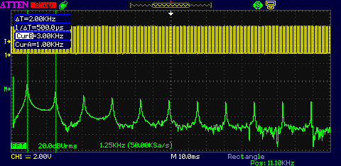
I fed a 500Hz staircase wave to the scope and switched the FFT to Blackman. Note that you have to adjust the timebase on the wave?before?you activate FFT in order to get a better FFT resolution. The more points captured, the better the resolution on the FFT is. Cursor A is adjusted to 0Hz (on the left) and Cursur B is adjusted to the second harmonic at 1kHz (on the right). The 500Hz peak stands out between the two cursors. I measured the FFT with my PicoScope and the FFT result is exactly the same. |
 |
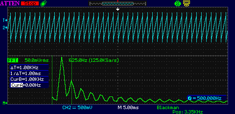
FFT on the scope's own 1kHz signal. The main frequency can be seen at Cursor A (1kHz) and the second harmonic at Cursor B (3kHz). The cursor measurements are spot-on compared to my PicoScope. Bug: when I activate Long Memory, the FFT's horizontal frequency scale is completely incorrect and cannot be used to determine where the frequency peaks are. The Rigol resets itself to normal memory depth when the FFT math function is activated. (Note that the Rigol has a horizontal scale bug which shows a large harmonic frequency peak at 500Hz.) |
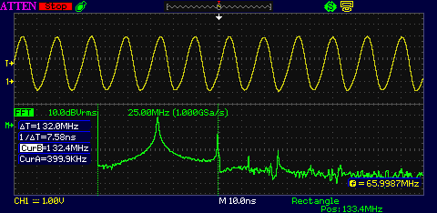 |
FFT using a high-frequency source on the input from a 66MHz crystal oscillator. The measurement is taken directly on the output of the oscillator can. The main 66MHz signal can be seen as a sharp peak at 66MHz and the harmonics are correct (Cursor B is at 132MHz). The output of the crystal oscillator is actually a square wave, but the harmonic frequencies are far higher than what the scope can measure, so the display is correct. |
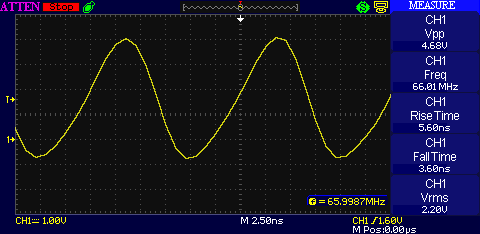 |
Back to the 66MHz signal with some associated automatic measurements. All measurements are correct. |
 |
Same 66MHz signal showing the configuration of the digital filter. |
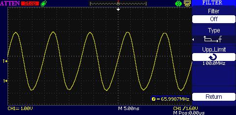 |
Here I set the upper frequency limit to 100MHz (filter turned off). |
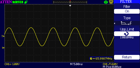 |
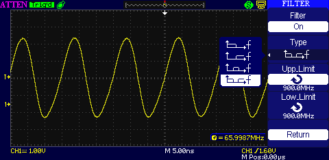
Here the filter is turned on, showing significant smaller signal due to the filter blocking the higher frequency harmonics. |
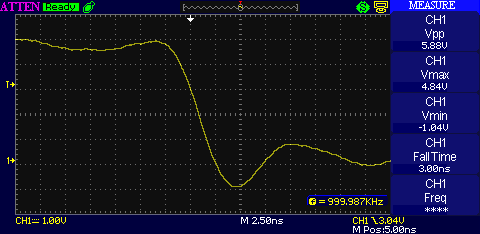 |
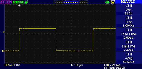
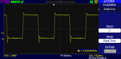
Testing the acquisition system with a 1MHz signal and triggering on the down slope. |
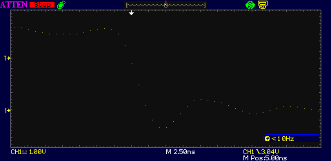 |
The same signal as above, but using dots instead of vectors. There is one dot at every nanosecond showing that the scope does indeed sample at 1GSa/sec. Note that the sampling rate is 500MSa/sec per channel when using two channels. The sampling rate also falls to 500MSa/sec when switching to Long Memory. |
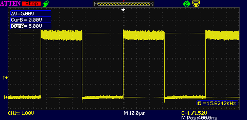 |
Here we have the 15kHz signal again, showing noise generated on the power line of the supply to the 74HC4040 binary counter. The counter does not have any decoupling capacitors connected to it, hence the very noisy power line. |
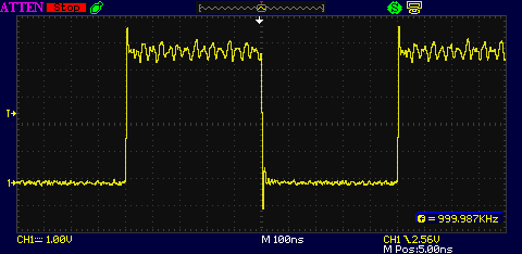 |
Switching to a different output on the 74HC4040 chip for a 1MHz signal. The input clock is 4MHz. Note the ringing as well as the noise on the power line again. |
 |
Back to the 15kHz signal, zoomed in to see the line noise once more. The cursors show 0V and 5V rails for reference. The "f" displayed in the lower right-hand corner is the frequency measurement. This is a hardware frequency counter and I have measured 158MHz frequencies with it. I am sure that it will measure higher frequencies as well. |
Here is a summary of Firmware bugs (for version?3.01.01.213) on the Atten ADS1102CML that I found:
- Equ Time mode sampling causes random dots on the display (see below for examples)?Fixed.
- Reference waves are not displayed (can be fixed, see below)?Fixed.
- Reference waveforms do not display correct voltage scale with 10X probes?Fixed.
- Horizontal FFT frequency scale is incorrect when Long Memory mode is selected
- Averaging sampling does not work at all.?Fixed.
 |
When I first unpacked the ADS1102CML I saw that the reference waves were not being stored. No matter what I did, I could not get the reference waves to display. Shown to the left is once such incidence. I was able to fix this issue by pressing the "Default Setup" button. Once this was pressed, reference waves worked and have worked ever since. Fixed: after the new firmware update I could not simulate this problem any more. |
 |
The screen to the left shows a 4MHz signal, correctly displaying the frequency and also shows the ringing on the leading and falling edges. Nothing wrong here. |
 |
Switching the Equ Time mode, shows the same signal as above (more or less), but there is something wrong with the way the sampling is done, causing random dots all over the display. This bug is present on most of the sample rates and waves done in Equ time mode. Fixed: new firmware solved this issue. |
 |
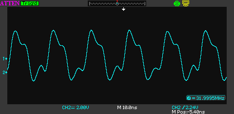
Another view of a 32MHz signal showing the Equ Time sampling bug at 5ns intervals. Note that it still correctly shows two distinct waveforms (the little bump in the middle of the wave). I verified the waveform with my 150MHz HP scope. I could not measure/detect the two distinct waveforms using the 50MHz Rigol, even in Equ Time mode. Fixed: new firmware solved this issue. |
Features I like
- I love the fact that you can configure the PRINT button to save the current image to disk immediately. You don't have to go into a menu to do the saving, you simply press the button and it will save the waveform to USB drive. It auto-increments the file name.
- It has separate position and sensitivity controls for CH1 and CH2. On the Rigol it is a major frustration to me to have to switch between the channels before I can change the position or sensitivity of the channel.
- The power cord is plugged into the back of the oscilloscope, not the side. Allows for easier placement on my bench next to other equipment.
- Power button is on the front, not the top, so I could squeeze it in below one of my shelves.
- The fan is very quiet. I cannot hear the fan of the ADS1102CML when it is sitting on my bench. In contrast, the fan on the Rigol DS1052E is really rather loud (and disturbing).
- The 7" screen is lovely. You don't feel cramped and placing measurements to the right does not obscure most of your signal.
Things that annoy me
- The positioning knob-speeds remain linear. If you turn the knobs (especially the horizontal position knob) the speed remains linear and you have to turn it many times to get the signal positioned where you want it. On the Rigol and the HP the knobs employ acceleration control where it detects you're turning it faster and jumps the position exponentially.?Fixed: new firmware now has accelerated adjustments if the knobs are turned faster and more accurate linear adjustments when the knobs are turned slowly.
- The oscilloscope seems to slow down a lot when triggering at long time bases. The menu's will not react until a time-base period has expired, even on auto-triggering.?Mostly fixed: the 'scope reacts a lot faster, but still exhibits slightly slower response times during 256-times averaging. This really is not an issue though.

